
|
Electronics
|

|
- Single sided PCB
 [35 x 110 mm] [1.38 x 4.33 inch]
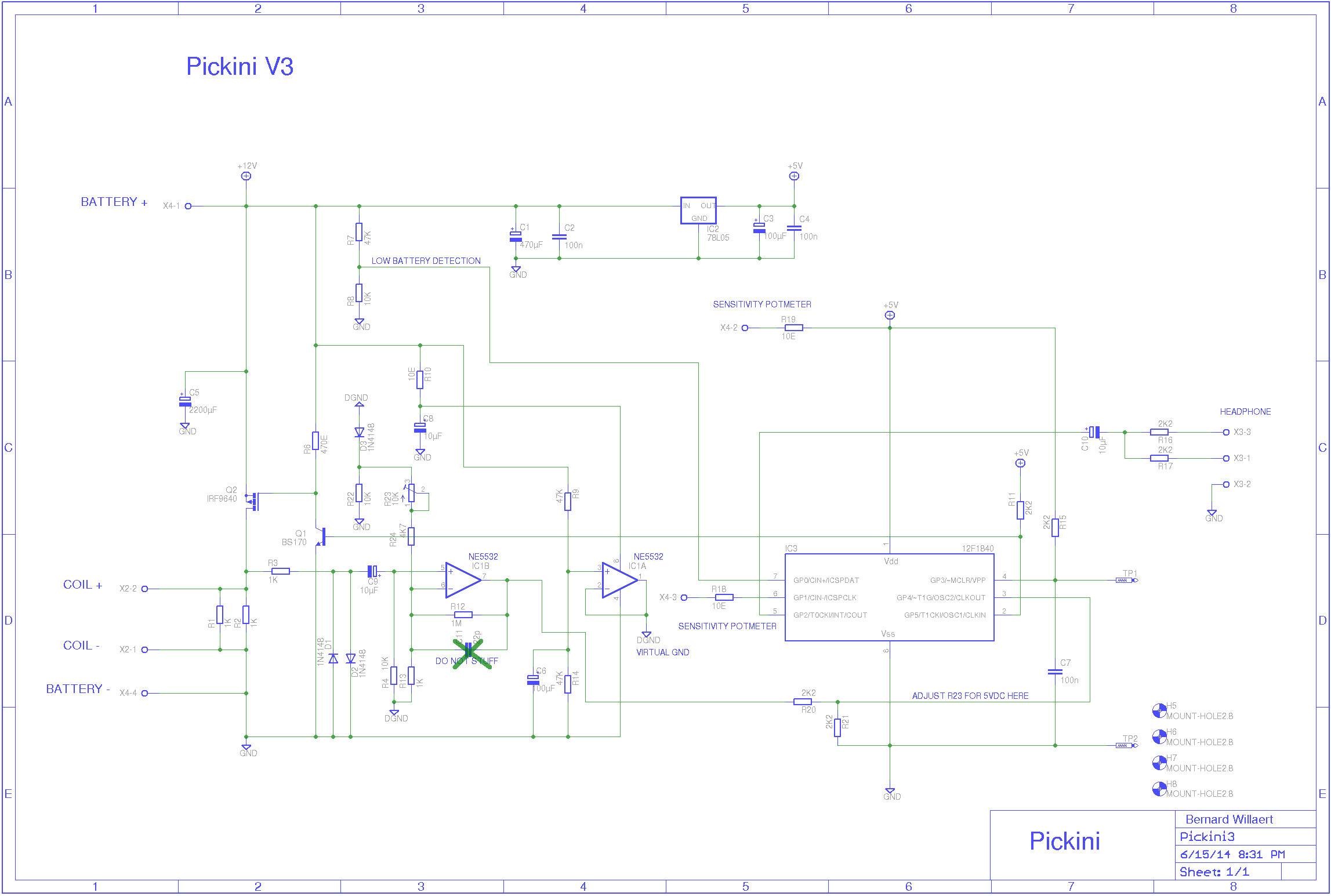
- Schematic diagram
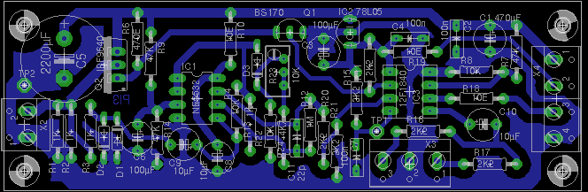
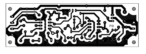
- Monochrome PCB picture - Cu side
- Monochrome PCB picture - Component side
- Eagle schematic file
- Eagle board file
- Adjustment:
Adjust the DC offset of the opamp output with multiturn R23:
Measure the DC voltage at pin 3 of the PIC12F1840 and adjust from low voltage until 5.3V is reached.
Stop adjusting when 5.3V is barely reached.
The voltage won't go any highter since it is clipped internally in the microcontroller with a diode to 5V.
When properly adjusted with a DC voltmeter, the waveform at pin 3 of the PIC looks like this:

- Pinpoint pushbutton:
A optional pinpoint pushbutton can be attached between testpoint TP1 and GND.
When this pushbutton is closed, the detector works in non-motion mode.
It does not continously track the incoming samples anymore but keeps a fixed reference.
Push the button when the coil is not over the target. Bring it over the target with the switch closed and it will
keep giving a detect sound even when the coil is not moving over the target.
- Parts list
| C1 | 470µF / 25V |
| C2 | 100n cer |
| C3 | 100µF / 25V |
| C4 | 100n cer |
| C5 | 2200µF / 25V |
| C6 | 100µF / 25V |
| C7 | 100n cer |
| C8 | 10µF / 25V |
| C9 | 10µF / 25V |
| C10 | 10µF / 25V |
| D1 | 1N4148 |
| D2 | 1N4148 |
| D3 | 1N4148 |
| IC1 | NE5532 |
| IC2 | 78L05 |
| IC3 | PIC12F1840 |
| Q1 | BS170 |
| Q2 | IRF9640 |
| R1 | 1K |
| R2 | 1K |
| R3 | 1K |
| R4 | 10K |
| R6 | 470E |
| R7 | 47K |
| R8 | 10K |
| R9 | 47K |
| R10 | 10E |
| R11 | 2K2 |
| R12 | 1M |
| R13 | 1K |
| R14 | 47K |
| R15 | 2K2 |
| R16 | 2K2 |
| R17 | 2K2 |
| R18 | 10E |
| R19 | 10E |
| R20 | 1K |
| R20 | 2K2 |
| R21 | 2K2 |
| R22 | 10K |
| R23 | 10K multiturn |
| R24 | 4K7 |
- PCB picture
On one of these first boards, the multiturn R23 was still a normal adjustment potmeter.
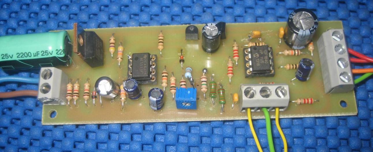
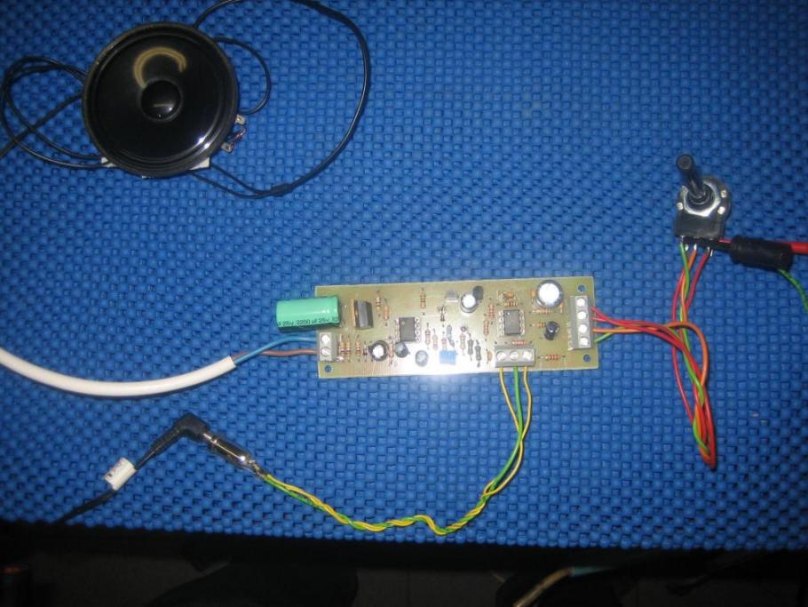
- PCB connected to coil, power supply and speaker
PICKINI home